|
Your Cart
|
|
Your cart is Empty
|
|
If you have a 1G chip with 2 images burned into it, one from 0000-3FFF, and the normal one from 4000-7FFF, the following is a procedure for the easy modification of your ECU in order to access that lower image.
Here is the bottom of a 1G EPROM ECU, showing the 28 pins of the socket. You will notice that pin #1 is at the upper left, and pin #28 is at the bottom left of the picture:
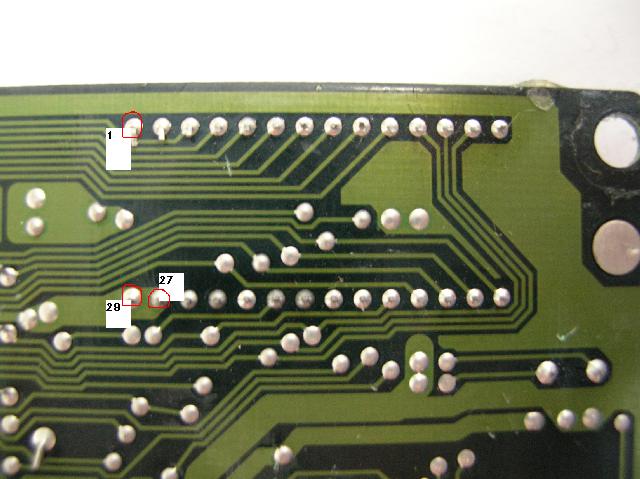
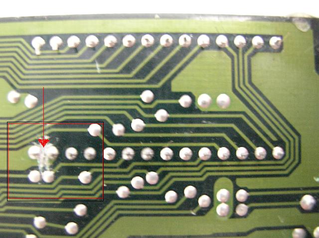
You will notice that there is a huge trace connecting pin #28 (+5 volts DC) to pin #27 next to it. What we need to do is remove that connection, gently using an EXACTO knife, so as to be sure not to cut any other nearby traces if you slip!
The finished cut should look something like this:
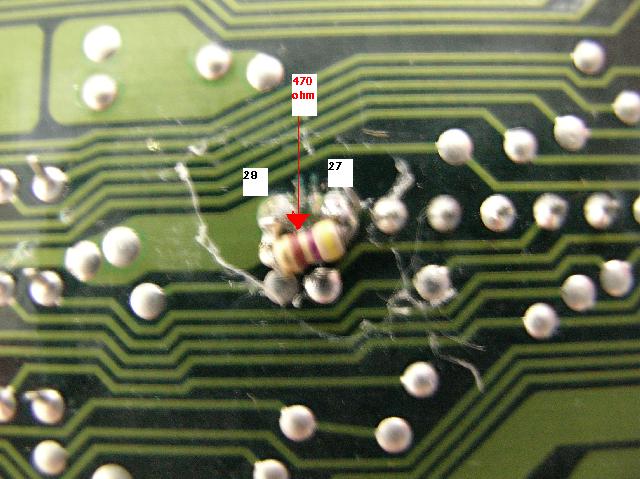
The next step is to bridge a 470 ohm 1/8 watt resistor across that cut:
The next step is to connect a piece of small gauge stranded wire to pin #27:
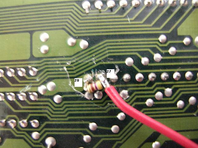
Todd Day raised the concern that RF interference from powerful transmitters could be received on the long wire to a switch, so I've included two optional components, that should eliminate any chance of this. You can simply solder a .01uF capacitor from pin #27 to ground, and loop a ferrite bead into the wire, which will bypass all the RF to ground:
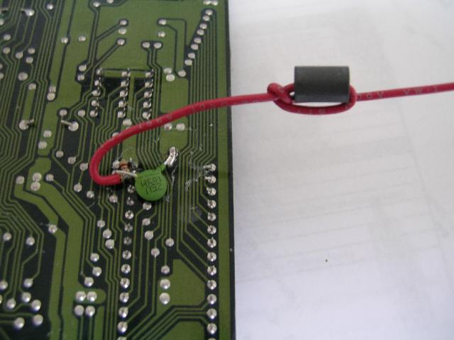
That's it! Now all that's left is to run the wire to any switch you like on the dash or console, to connect the wire to ground when you want the lower maps!
|
|